The smaller the diameter, the tougher to manufacturer
Isn’t it interesting that the smaller the end mill diameter the higher the price? There is a reason for that, micro diameter end mills are a breed of their own. The smaller the diameter the more precise you need to be. The tolerances are tighter making the level of difficulty greater. They also require special CNC grinding machines dedicated solely to the micro focus with some machines limiting the largest diameter to .080”. These machines require the tightest of tolerances, extreme accuracy, as well as temperature and vibration control. The manufacturing that goes on inside of these machines is done in much tighter quarters than compared to the CNC grinding machines made to manufacture end mills up to and over 1” diameter.
So what is it exactly that determines a good end mill from a bad one? You would think that since most manufacturers have access to the same CNC grinding machines, the same programming software, the same grinding wheels, etc, that one end mill can’t differ all that much from the next… right? After all, look at all the differentiating factors you can specify when ordering. We can specify the diameter size, end shape, number of flutes, length of cut and overall length. We can specify geometry for the type of material we are milling, we can order variable helix and index, we can even order with different tool coatings for our particular application. Unfortunately the factors that the average consumer has control over only scratch the surface of the decisions that are made during the manufacturing process. What most people don’t realize is that there are up to 21 different attributes and geometric decisions made during the end mill manufacturing process. This goes for micro diameters down to .001” up and to diameters over 1”. Each attribute has its own set of variables leaving the combinations that can be created on one particular size end mill far too numerous to count. However by industry standards just about all variations can be considered acceptable or “within end mill tolerance”. But just because some of these variation can pass inspection, doesn’t mean they should pass inspection.
There are a great number of decisions made at the manufacturing level behind closed doors that the average consumer has no control over. These decisions include land widths, flute depths, core diameter, axial clearance angles, rake angles, gash angles and web thickness just to name a few. It’s a combination of these different attributes that make one end mill work great and another not so great. It’s up to each individual manufacturer to determine what is acceptable and what is not. Each manufacturer determines how tight or how loose they will hold this criteria and how often they will make adjustments during the manufacturing process to hold geometry exactly where it should be.
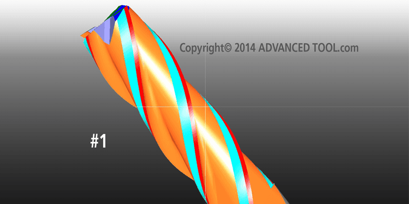
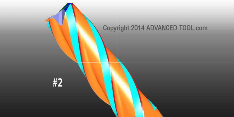
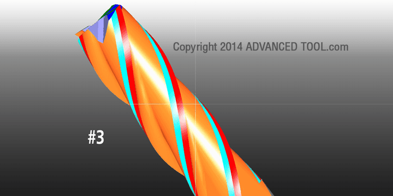
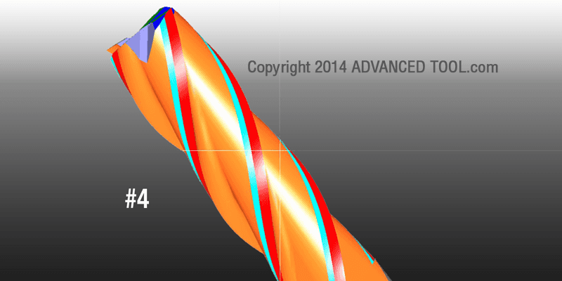
Below are illustrations demonstrating variations of a primary/secondary land width. All could technically be considered “within end mill tolerance”, but each will work differently. The red line is the primary land in each of the illustrations below, you will notice that the width (thickness) changes in each of the illustrations.
Illustration #1 is an ideal ratio for a primary and secondary land width.
Illustrations 2-4 would “pass tolerance” by industry standards but would not necessarily work to the best of the end mill’s ability.
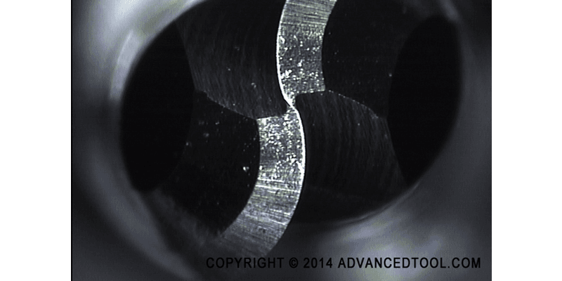
The picture below shows a view of a web & gash on a .040” two flute ball end mill. This is an example of what you want to see when viewing the top of a micro ball end mill. You can notice a white line running in almost an “s” pattern across the top of the end mill. This is your cutting edge.
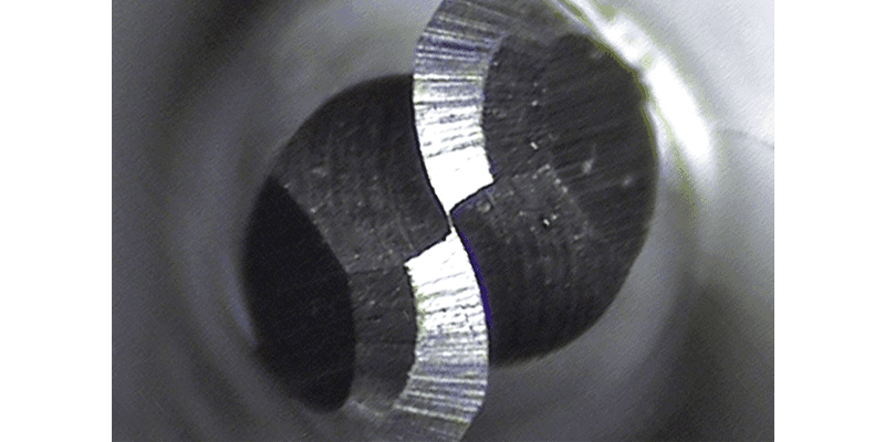
Whereas the next photo shows a web or gash that is too thin. There is not enough “meat” in the center of the end mill. In manufacturing terms we call this “breaking center”. This end mill will not perform as well the end mill shown above.
It is important to understand that each end mill manufacturer has their own recipe or “secret sauce” regarding what they feel is good or bad geometry combinations. These combinations are based on their experience working with different materials. Their recipe may also be based on their position in the marketplace. If their business model is price driven then some attributes may be eliminated in order to meet price points. For instance, in micro end mill manufacturing it is common to see some manufacturers skip adding a secondary land and only manufacturing with a primary land. This may save on the cost of the end mill upfront, but could cost you quite a bit on the back end in parts generated per end mill.
One of the biggest issues in micro diameter end mills can also be nicks or breakage along the cutting edge during handling. Carbide is fragile and breaks easily as it is. However, when you are working with diameters that can’t be seen by the naked eye, an operator might accidentally damage a cutting edge and not even know it. The only way to see that any damage is by viewing the end mill under magnification.
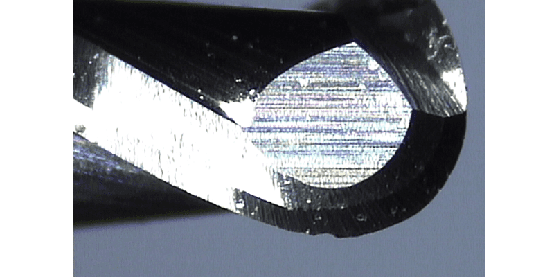
This next photo shows a .030” diameter two flute end mill with a small nick on the bottom cutting edge, this nick occurred during handling. Tool coating is component of the manufacturing process that actually requires more handling of the end mill than the manufacturing process. During manufacturing a carbide blank goes in the machine as a prepped blank and comes out a complete end mill. However the coating process requires handling the end mill multiple times; for cleaning, for the coating itself and sometime for post treatments. This handling leaves more opportunities to nick a cutting edge. That is why it is critical for manufacturers have in-house inspection processes in place and/or partner with tool coaters that address these major concerns.
It’s up to the consumer to have the knowledge necessary to select the proper end mill or end mill partners in order to get the most out of their milling applications. Each year manufacturing engineers spend countless hours testing various new and improved end mills that hit the market in hopes to attain better results, reduce their costs, and add more profit to their bottom line. Testing and finding performance improvements is the nature of the beast in manufacturing. If you don’t have a culture of continuous improvement, your competition will eat your lunch. Time is money, so engineers are in constant search of faster speeds & feeds, longer tool life, and the best possible part finish… all while trying to reduce the total overall costs. This is not an easy feat, because it’s rarely a one size fits all model. Not all applications are created equal. What works in one environment and setup may work completely different in a similar environment and setup elsewhere. Unfortunately the sheer number of end mill manufacturers and end mill combinations in the market is mind boggling. Having a better understanding of good and bad geometry helps in that selection process.
At Advanced Tool Inc we never cut corners and you will never see sloppy end mill geometry. Let us take a look at your next end milling project.

